
A voltage reading at the landscape transformer leaves two important possibilities open: the installed circuit may be interrupted, or the source and its connections may fail to sustain suitable output when current flows. Replacing fixtures before separating those possibilities can leave the real fault untouched.
First, clarify what “shows output” means. An illuminated indicator, a digital display, and a voltage measurement provide different evidence. Then identify the first accessible low-voltage connection serving the lights. The useful diagnosis follows what each observation proves—from voltage at one location to operation through a complete circuit.
Open-Circuit Voltage vs Usable Power Under Load
Treat an unloaded voltage reading as evidence about the measurement point, not clearance for the entire system. A meter needs very little current to display a value. Operating the lights demands more from the source and every connection in their circuit.
Two different failures can produce the same apparent contradiction. An interrupted cable or connection can leave voltage present at the transformer while preventing current through the fixtures. A resistive connection can allow an unloaded reading but cause excessive voltage loss when current flows.
The measurement location matters. A reading at the transformer does not establish whether voltage reaches a fixture through the installed cable. A reading taken with the outdoor runs disconnected also cannot establish what happens when those runs are included.
These distinctions narrow the problem within broader transformer troubleshooting: the source may have no-load voltage, yet its loaded performance and the external circuit remain unproven.
Even “the lights were connected during the reading” needs qualification. If a shared connection is open, the lights may be physically attached without drawing current. That is not a meaningful load test. Record where the reading came from, what was connected, and whether any fixture actually operated.
The First Connection After the Transformer
Start with the earliest accessible connection that could interrupt power to all the dark fixtures. With the transformer’s supply disconnected, identify where its low-voltage output joins the installed lighting cable. This could be a user-accessible secondary connection, an approved plug connector, a hub, or an external splice.
Some installations have continuous cable leading away from the transformer without a separate first splice. Follow the visible arrangement instead of assuming there must be a connector beside the enclosure.
Look for evidence that changes the next decision: a cable pulled out of position, a cracked connector housing, corrosion at an accessible interface, or heat damage. Do not loosen connections while energized, pull on conductors to provoke a response, or cut open a sealed connector for inspection.
If visible deterioration is present, corroded outdoor splices deserve closer assessment before individual fixtures become the focus. However, a connector’s clean exterior does not establish that its internal contact is sound.
Position determines whether that defect explains the outage. A damaged connector serving one fixture or one branch cannot, by itself, explain darkness on an independent run. Before treating a visible flaw as the answer, establish which lights depend on it.
Common Return and Shared-Splice Failures
A shared-connection diagnosis only fits when every affected fixture depends on that connection. Each fixture needs a complete circuit through both low-voltage conductors; a sound connection on one cannot compensate for an interruption on the other.
Where several lights share a return connection, opening that connection can stop all of them. The same applies to a shared supply connection before the branches divide. Voltage can remain at the transformer because the interruption lies beyond the measurement point.
Here, “common” means the applicable secondary circuit connection. It does not mean earth, the equipment grounding conductor, or the home’s mains neutral. Those are not substitutes for a missing low-voltage circuit conductor.
Landscape fixtures are generally connected as parallel loads. One failed lamp therefore does not normally interrupt every other lamp. A shared cable termination or splice is different: several otherwise functional fixtures can depend on that single connection.
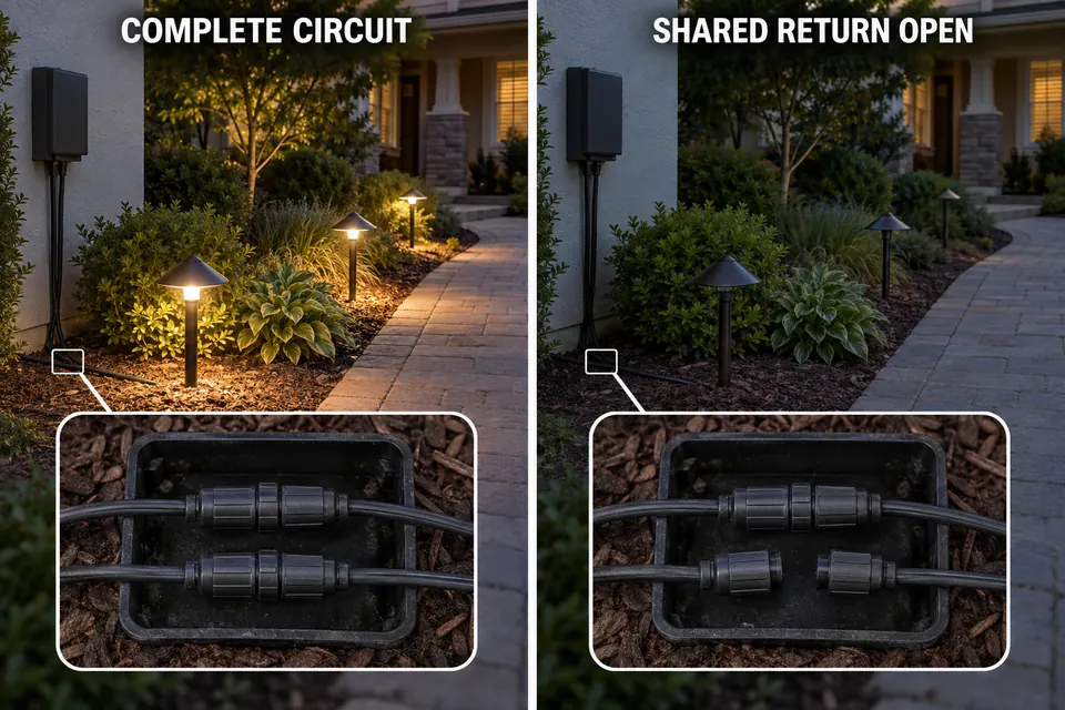
The shared portion must actually exist in your installation. Separate runs may leave the transformer independently, with no external splice common to all of them. A break after a branch point affects only the fixtures that depend on that segment.
“All dark” makes genuinely shared points worth investigating. It does not identify a particular common terminal, conductor, or splice as the fault.
Testing With One Known-Good Short Run
The useful test excludes the original outdoor network and asks whether the source can operate one compatible fixture through a short, known-good cable. Leaving the original runs connected preserves the uncertainty the test is meant to remove.
Before the Test
Both the fixture and cable must be independently known good. Moving an unverified fixture from the dark yard onto another cable simply moves an uncertainty.
Compatibility includes the required voltage, AC or DC output, and any manufacturer-specified minimum-load or control requirements. One small LED fixture is not a valid universal test load for every transformer. If compatibility is uncertain, a dark test fixture cannot reliably distinguish a source problem from an unsuitable load.
Fix Boundary: Use only manufacturer-designated, user-accessible low-voltage connections. Disconnect supply before every connection change. If the test requires mains-compartment access, altering fixed wiring, or an unclear terminal arrangement, have a qualified professional perform it. Never bypass controls or protection.
Follow the model’s approved connection provisions:
- Confirm the test arrangement. Verify that the fixture, short cable, and required operating conditions are compatible with the transformer.
- Disconnect supply and exclude the original network. Use the approved connection arrangement so the outdoor runs are outside the test.
- Connect and secure the short test run. Restore required covers before supplying power and using normal operating controls.
- Observe, then disconnect supply again. Record whether the fixture operates steadily, stays off, or becomes unstable before making any further connection change.

What the Result Actually Establishes
Interpret the result only after the test conditions are confirmed.
| Observation | What it supports | What remains unresolved |
|---|---|---|
| Compatible test fixture operates steadily | The source and included connections can operate this small load; investigate the excluded installation | Full-load performance and the exact external fault |
| Known-good, compatible test fixture stays off | The original buried network is not needed to reproduce the failure | Source, included output connection, operating state, or an unverified test condition |
| Test fixture flickers, drops out, or triggers protection | Operation is unstable in this arrangement; stop repeated testing | The cause requires model-specific assessment |
A working test light clears only the path and load actually tested. If the arrangement excludes an external splice, it has not proved that splice sound. Nor has one small load certified the transformer at the installed system’s full demand.
A failed test needs equally careful wording. Until compatibility, the included connections, and operating conditions are established, “the transformer is bad” goes beyond the evidence. Avoid replacing it on that result alone.
When Cable Tracing Needs a Professional
A successful small test followed by no useful accessible clue is a reason to arrange cable tracing, not to start digging. Attention has shifted toward the excluded installation, but no buried break has been located.
Unknown routes, inaccessible junctions, hidden branches, and cables beneath walkways require proper locating and testing. Opening buried connections along a guessed route can create additional repair points without resolving the original fault.
A landscape-lighting professional can assess low-voltage cable paths. Failed or unstable valid tests may instead require manufacturer support or electrical assessment. The boundary for calling an electrician about outdoor lighting becomes especially clear when mains access, fixed wiring, or an uncertain supply-side condition is involved.
Stop further testing if there is melting, a burning odor, water inside electrical compartments, or protective-device operation. Repeated resets do not locate the fault.
Provide the transformer model, whether “output” meant an indicator or measurement, and any already-known measurement location and load condition. Include whether every light stopped together, what was visible at accessible connections, and the short-run result if safely obtained.
Any confirmed connection repair must restore its approved weatherproof protection. Choose the next intervention by the test boundary: trace the excluded installation after a successful small test; seek assessment of the source and included connections after an unsuccessful valid test. A voltage reading alone justifies neither excavation nor transformer replacement.
For the underlying relationship between connection resistance and load performance, see Fluke’s explanation of voltage-drop diagnosis. (www.fluke.com)