
The walkway lights look normal until the planting-bed lights switch on. Then the same walkway fixtures become noticeably dimmer—and recover when the other group switches off.
Compare those same fixtures with the second zone off, on, and off again before changing transformer capacity. A repeatable response points toward a shared electrical constraint, but limited capacity, a weak supply, and a poor shared connection can produce similar symptoms.
First distinguish a brief dip during switching from dimming that remains while both zones operate. The sustained change is the focus here.
Why a Second Zone Changes the Electrical Load
Zone B can affect zone A wherever their electrical supply paths overlap. Switching B on adds demand to the shared transformer and increases current through any connection or cable section serving both groups.
Resistance in that shared path produces greater voltage loss as current increases. A marginal connection may therefore seem adequate with A alone but become troublesome when B joins it. The transformer’s output may also fall under the additional demand.
A “zone” is simply a group operated together. Separate controls do not establish separate electrical supplies, and two zones may share wiring before their routes divide.
The useful distinction is whether the second zone changes the first. If one run stays dim regardless of the other zone, follow that persistent difference instead of assuming a combined-load problem.
Also separate appearance from measurement. Some LED drivers maintain similar brightness across a range of input voltages; others dim, flicker, or drop out as their supply becomes unsuitable. The visible response identifies where to investigate, but it cannot tell you the voltage or capacity by itself.
Shared Transformer vs Shared Connection
Locate the last part of the supply path that both zones share. It may be the transformer’s output terminals, a common terminal, a feeder cable, or a splice before the groups separate. That shared portion is the starting point for explaining why switching B affects A.
Separate screws on a terminal block do not necessarily provide independent capacity. Different voltage taps may still belong to the same transformer winding and remain subject to shared limits.
The electrical comparison asks where the additional loss appears. If a source-side reading stays stable while voltage farther downstream falls with both zones on, the intervening connection or cable path deserves attention. If output falls at the source, loading, transformer condition, and the upstream supply remain possibilities.
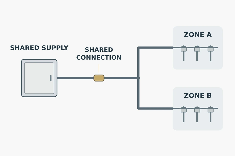
Measurement location matters. A reading taken on the transformer side of a poor terminal interface may miss the loss between that terminal and the connected cable. A qualified person needs to compare suitable test points under the same operating conditions.
Visible looseness, damaged insulation, or corrosion at an outdoor splice strengthens the case for connection assessment. A clean exterior, however, does not prove the connection is electrically sound.
If the zones already have separate transformers, shared low-voltage transformer capacity cannot explain their interaction. A shared upstream supply may need an electrician’s assessment. Likewise, one group remaining visibly steady does not clear the shared source: different fixtures can respond differently to the same voltage change.
The Zone Combination That Reproduces the Drop
Keep zone A unchanged and use the existing controls to add and remove B’s load. Choose the same few fixtures in A and observe them from one position under similar ambient light.
Field Check: Use normal controls for this comparison; terminal access, conductor changes, and live measurements require appropriate competence and equipment. Stop testing if there is a burning odor, damaged insulation, or repeated protective tripping.
Establish how A operates alone and how B operates alone. Then observe A alone, switch B on while A remains on, and switch B off again. Allow each state to settle without rapidly cycling the controls.
Keep brightness settings and connected fixtures unchanged throughout the comparison.
| Operating state | Observation to record | What it helps establish |
|---|---|---|
| A only | A’s baseline brightness | Whether A is already weak |
| B only | B’s baseline behavior | Whether B has an independent symptom |
| A + B | Change in the same A fixtures and whether it persists | Whether combined operation triggers the effect |
| A only again | Whether A returns to its baseline | Whether the change follows removal of B’s load |
If B also behaves poorly alone, its own load or supply path needs assessment before treating this as a simple combined-capacity problem. If both groups operate normally alone but A dims when they run together, the shared-path comparison becomes more useful.
Record whether all of A dims or only its distant fixtures, and whether brightness recovers while B remains on. A short switching dip and a sustained loss are different results.

If recording with a phone, lock exposure. Otherwise, the camera may darken the entire image when B adds light, creating an apparent drop that the fixtures did not produce. Added illumination can also change your perception, so visual results may need electrical confirmation.
Recovery when B switches off supports a load-dependent interaction, but does not identify the failing component. If normal controls cannot operate the groups separately, leave isolation to someone qualified rather than disconnecting energized cables.
Capacity on Paper vs Real Output
Check capacity against the combination that causes the drop. Add the actual input load of every fixture operating in that state; a few higher-output accent lights may demand more than a longer row of small path lights.
Use the rating method specified for the equipment. LED watts and volt-amperes, or VA, are not automatically interchangeable. Where fixture documentation supplies VA or transformer-loading guidance, use it rather than forcing everything into a wattage estimate.
When checking the total load on one transformer, include both the overall limit and any individual output, circuit, or terminal limits. Being below the total rating does not establish that every connection or output is appropriately loaded.
Headroom means capacity remaining within the manufacturer’s operating guidance. No single percentage overrides the installed equipment’s instructions, and spare capacity does not compensate for a damaged connection.
The deciding comparison is delivered voltage with A alone versus A+B, measured at the same suitable points. Results must be assessed against the fixtures’ documented input ranges.
An excessive combined load supports reducing or separating demand. A load within the applicable limits leaves connection loss, distribution, and equipment condition to resolve. A satisfactory no-load reading cannot settle those questions.
Splitting Loads Without Guessing
Correct a confirmed connection problem before treating additional capacity as the remedy. Reducing demand may make a marginal connection’s symptom less obvious while leaving the defect in place.
Separating cable runs and separating power supplies accomplish different things. Independent runs from the same transformer can reduce current through a previously shared feeder, but the transformer still supplies the combined fixture load. Moving a cable to another terminal does not inherently create more capacity.
A second transformer becomes a reasonable design option when the required simultaneous load exceeds the existing unit’s permitted capacity, or when a verified distribution problem supports supplying the groups independently. A transformer that performs poorly within its intended operating limits needs assessment rather than having its weakness concealed by permanently reducing the load.
Independent supplies require properly separated low-voltage circuits. Do not parallel their outputs or leave a shared return joining the separately supplied zones. The new arrangement also needs suitable supply power, protection, placement, and fixture compatibility under the equipment instructions.
After correction, repeat A alone, B alone, and both together. The repair is demonstrated when the previously affected fixtures remain stable as the other zone switches on. Leaving B off only removes the condition that exposed the problem.
For manufacturer guidance on load division and keeping power-supply outputs separate, see FX Luminaire’s PX transformer instructions.