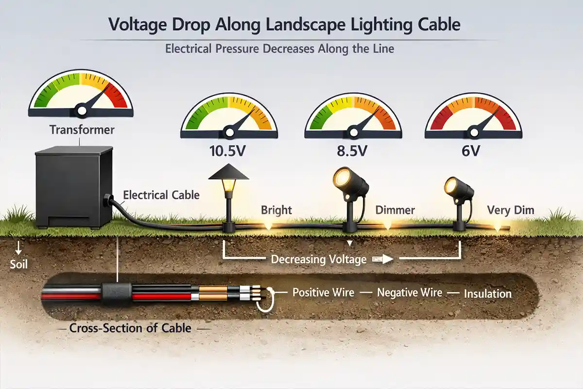
Outdoor lighting systems distribute electricity through cables in a way that closely resembles fluid moving through a pipeline. As electrical current travels through copper wiring, a portion of the energy naturally converts into heat because of electrical resistance within the conductor. This gradual energy loss causes the voltage available to decrease as distance from the transformer increases.
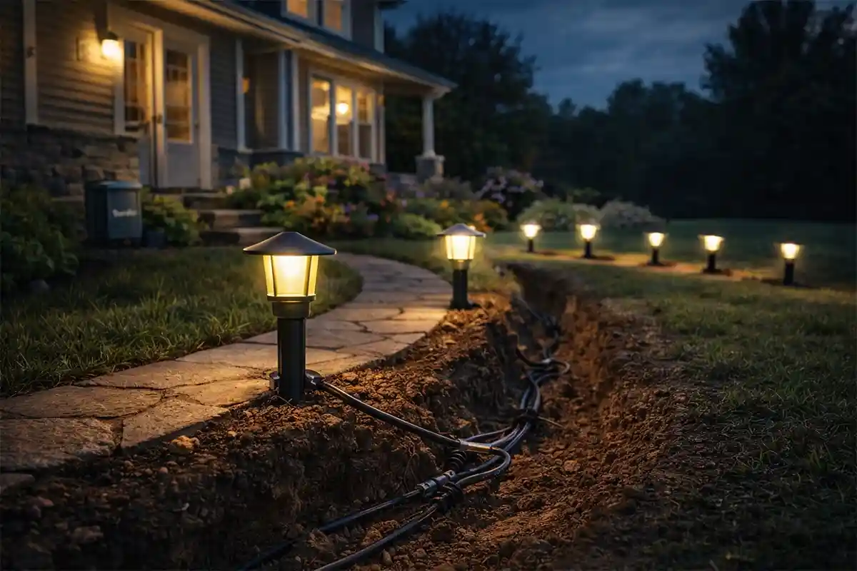
The result is a common landscape lighting symptom: fixtures near the transformer appear bright and stable, while lights farther along the cable become dim or stop working entirely. The issue is rarely caused by a single defect. Instead, it typically develops from the combined effects of electrical resistance, wiring layout, fixture load, and environmental exposure.
In most residential landscape lighting systems, transformers supply 12 volts of alternating current. Lighting fixtures depend on receiving voltage within a specific operating range to maintain proper brightness. LED landscape fixtures generally require about 10.5–12 volts for stable operation. When voltage drops below this range, brightness decreases or electronic drivers may shut down temporarily.
Electrical design standards commonly recommend limiting voltage drop to 3–5 percent across a circuit. In a 12-volt lighting system, this means the voltage at the final fixture should remain above roughly 11.4 volts. When the drop exceeds this threshold, differences in brightness become noticeable.
Multiple environmental factors can accelerate this process. Long cable runs increase electrical resistance. Thin wiring raises resistance even further. Corrosion from soil moisture may degrade connectors over time, introducing additional resistance points in the circuit. As these small inefficiencies accumulate, fixtures at the far end of the lighting line receive progressively less electrical energy.
Understanding the underlying electrical mechanism makes it easier to diagnose and correct the imbalance before the entire lighting system becomes unreliable.
The Science Behind the Phenomenon
Electricity flows through metal conductors because of a difference in electrical potential known as voltage. Inside copper wiring, moving electrons collide with atoms within the metal lattice. These interactions produce resistance, converting some electrical energy into heat and gradually reducing the available voltage along the wire.
This behavior is described by Ohm’s Law, which links current, resistance, and voltage. The longer the conductor and the greater the current flowing through it, the larger the resulting voltage loss.
Copper wiring used in landscape lighting systems has measurable resistance values:
-
12-gauge copper wire: ~1.6 ohms per 1000 feet
-
14-gauge copper wire: ~2.5 ohms per 1000 feet
-
16-gauge copper wire: ~4.0 ohms per 1000 feet
Weather exposure, loose connections, and faulty sensors are common causes of outdoor lighting problems.
Although these values appear small, resistance becomes significant when multiple lighting fixtures draw current along a long cable run. Each fixture consumes electrical power, leaving slightly less voltage available for the remaining fixtures farther along the circuit.
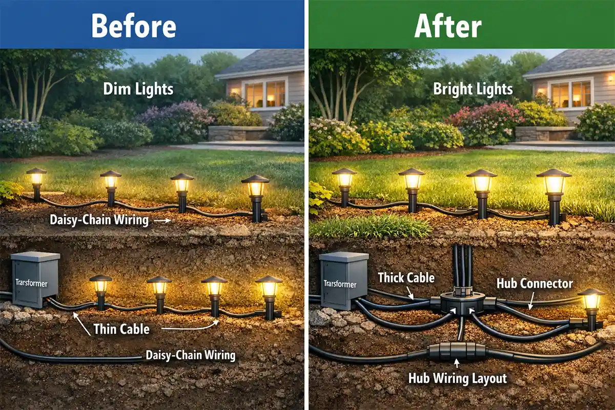
Electrical load distribution also influences system behavior. Many outdoor lighting systems are installed using daisy-chain wiring, where fixtures connect sequentially along a single cable. In this configuration, each fixture removes some electrical energy before the next one receives power.
Environmental exposure further complicates electrical performance. Moist soil and oxygen gradually oxidize exposed copper connectors. Corrosion layers increase electrical resistance, causing additional voltage loss at connection points. Even small increases in resistance can noticeably affect low-voltage lighting circuits.
Electrical instability created by uneven voltage may also lead to brightness fluctuations or inconsistent operation. Similar electrical behavior is explored in Flickering Outdoor Lights: Common Causes, where unstable voltage delivery disrupts normal lighting performance.
Processes That Trigger the Problem
Voltage loss develops gradually as several physical and installation-related processes combine within a lighting system.
Long Cable Runs
Electrical resistance increases proportionally with conductor length. Landscape lighting installations often extend across driveways, pathways, and garden areas, sometimes exceeding 150–200 feet of cable. As current travels through longer wires, the cumulative resistance reduces voltage delivered to distant fixtures.
Small Wire Gauge
Thin conductors carry higher resistance than thicker wires. Many entry-level landscape lighting kits include 16-gauge cable, which performs adequately for short runs but can cause significant voltage drop across large properties. Thicker cables such as 12-gauge wire dramatically reduce resistance and maintain higher voltage over longer distances.
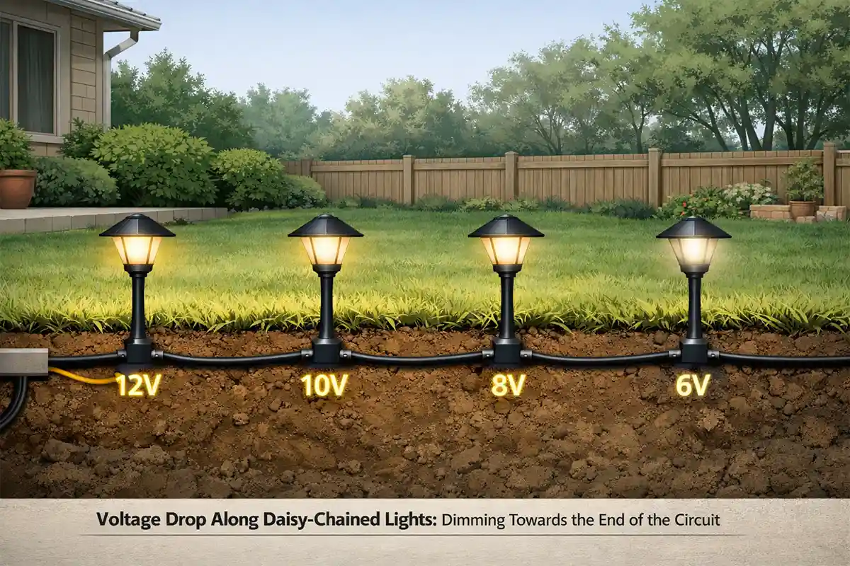
Sequential Fixture Wiring
The most common installation method connects lights sequentially along the cable. Each fixture draws power before the next fixture receives electricity. This distribution pattern causes progressive voltage reduction as current moves along the circuit.
Transformer Load Imbalance
Landscape lighting transformers have maximum wattage ratings. When too many fixtures connect to a single output, the transformer may operate near its capacity. Increased electrical load raises current flow through the cable, which increases voltage drop proportionally.
Connector Corrosion
Outdoor environments expose wiring connectors to moisture, soil minerals, and oxygen. These conditions promote oxidation on copper surfaces. Corroded connectors introduce localized resistance points that reduce electrical efficiency.
Environmental Electrical Effects
Heavy rainfall, soil saturation, and seasonal temperature changes can slightly alter electrical conductivity within outdoor circuits. These environmental conditions may accelerate corrosion or worsen existing resistance issues.
Electrical irregularities produced by these factors occasionally interact with protective devices. Ground-fault interrupters may detect abnormal electrical behavior when system imbalance becomes severe. This protective mechanism is discussed in Outdoor Lights Tripping GFCI Outlets, where electrical irregularities trigger safety shutdowns.
Practical Solutions Based on the Underlying Mechanism
Correcting power loss at the end of a lighting circuit involves reducing resistance, improving electrical distribution, or adjusting system voltage levels.
Upgrade to Lower-Gauge Cable
Thicker copper conductors significantly reduce resistance. Replacing 16-gauge cable with 12-gauge wiring can reduce voltage drop by 30–40 percent over long runs, helping maintain consistent brightness throughout the system.
Reduce Circuit Length
Shorter wiring distances reduce cumulative resistance. Dividing large lighting systems into multiple branches allows electricity to reach fixtures more efficiently.
Use Hub Wiring Layouts
Instead of connecting lights sequentially, hub-style layouts distribute power from a central junction point to smaller fixture groups. This design prevents early fixtures from consuming voltage before downstream fixtures receive power.
Balance Transformer Loads
Transformers often include multiple output terminals. Dividing fixtures evenly across these outputs reduces electrical load on any single circuit path.
Adjust Transformer Voltage Taps
Many landscape lighting transformers include adjustable voltage taps such as 12V, 13V, and 14V outputs. Supplying slightly higher voltage compensates for predictable voltage loss along longer wiring runs, ensuring distant fixtures still receive sufficient electrical pressure.
Replace Corroded Connectors
Weather-damaged connectors should be replaced with waterproof gel-filled connectors designed for outdoor electrical systems. Improved contact surfaces reduce resistance and restore efficient current flow.
Check Wattage Limits
Total fixture wattage should remain within 80 percent of the transformer’s rated capacity. Maintaining this margin prevents excessive current draw that would otherwise increase voltage drop.
A deeper explanation of electrical voltage loss in outdoor lighting systems can be found in Voltage Drop in Outdoor Lighting Systems, which examines conductor resistance and circuit design in greater detail.
Processes and Practical Solutions
| Process | Reaction or Mechanism | Result | Recommended Fix |
|---|---|---|---|
| Long wiring distance | Electrical resistance accumulates along the cable | Lower voltage reaches distant fixtures | Shorten cable runs or add additional transformer branches |
| Thin wire gauge | Smaller conductors produce higher resistance | Lights at end of line appear dim | Upgrade to thicker 12-gauge landscape lighting cable |
| Daisy-chain wiring layout | Early fixtures draw current before later ones | Progressive brightness loss | Use hub wiring or split circuits |
| Overloaded transformer circuit | Excess current increases voltage drop | Uneven lighting across the system | Balance fixtures across multiple transformer outputs |
| Corroded wire connectors | Oxidation increases electrical resistance | Intermittent or weak lighting | Replace connectors with waterproof outdoor connectors |
| Voltage loss over distance | Electrical pressure declines along long circuits | Final fixtures fail to illuminate | Use higher transformer voltage tap such as 13V or 14V |
Scientific Questions
Why do lights closest to the transformer appear brighter?
Voltage is highest near the power source. As current flows through wiring and fixtures, resistance gradually reduces the electrical pressure available farther along the circuit.
Does thicker cable really improve brightness?
Yes. Lower-gauge wires have lower electrical resistance, allowing more voltage to reach distant fixtures without significant loss.
Can LED lights still suffer from voltage drop?
Yes. Although LEDs consume less power, their drivers require a minimum voltage range to operate correctly. When voltage falls below this range, brightness decreases or fixtures shut off.
Why does corrosion make voltage drop worse?
Oxidation creates a resistive layer on metal surfaces. This additional resistance restricts electrical flow and increases voltage loss at connection points.
Diagnostic Checklist
The following observations often indicate voltage drop within an outdoor lighting system:
-
Lights near the transformer appear brighter than lights farther away
-
Final fixtures in the circuit occasionally fail to turn on
-
Brightness improves when several lights are temporarily disconnected
-
Wiring runs extend across large sections of the property
-
Small-gauge landscape lighting cable is used for long runs
-
Outdoor connectors show corrosion or discoloration
-
Transformer wattage rating is nearly equal to total fixture wattage
Key Scientific Insight
Power loss at the end of outdoor lighting circuits is typically caused by voltage drop created by electrical resistance in long wiring runs. As current travels through copper conductors and fixtures draw power along the line, available voltage gradually decreases. Improving wiring design, upgrading cable size, balancing circuit loads, and adjusting transformer voltage taps restore consistent brightness across the entire lighting system.
For additional guidance on electrical system design and conductor performance, resources from the National Electrical Manufacturers Association provide technical standards for electrical equipment and wiring practices.