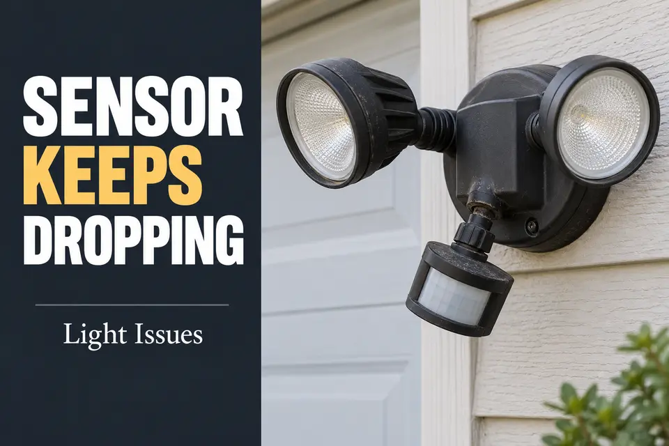
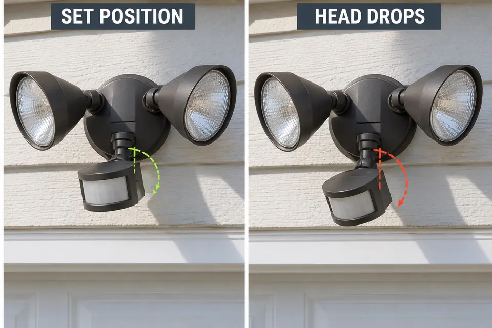
A motion-sensor head that can be aimed correctly but later points at the ground has a holding-force problem before it has a detection problem. If gravity, wind, or normal vibration changes the head’s physical angle, the detection zone moves with it. Sensitivity adjustments cannot stabilize a joint that no longer holds.
Start by photographing the sensor from the side immediately after aiming it. Include a fixed part of the fixture or wall in the frame so a small change becomes visible. A removable reference mark beside the joint can also help, provided it does not obstruct the joint or sensor lens.
Recheck the position without touching the head. If it repeatedly returns to the same lower or sideways angle, inspect the aiming hardware. Do not respond by tightening every visible part as hard as possible. The joint may only be loose, but it may also have damaged threads, worn friction surfaces, a cracked housing, or a locking collar that can no longer seat correctly.
Loose Aim vs Failed Detection
The first decision is physical: does the sensor stay exactly where it was aimed? Testing its coverage before answering that question can produce a false diagnosis.
Photograph the side profile after positioning the head, then check it after several normal operating cycles or a period of wind. Look for more than a dramatic drop. A small downward sag can pull the far edge of the detection zone several feet closer to the wall. Sideways rotation can move coverage away from a walkway and toward a driveway, shrub, or neighboring property.
| What you observe | More likely condition | First useful check |
|---|---|---|
| Head sits lower than in the reference photo | Joint slips under its own weight | Inspect the locknut, collar, or knuckle |
| Head rotates after wind | Joint lacks rotational holding force | Check seating and visible joint wear |
| Head remains fixed but misses movement | Detection problem rather than loose aim | Follow a broader sensor diagnosis |
| Entire fixture moves with the head | Mounting problem, not just the sensor joint | Stop and inspect the fixture attachment |
When the head remains fixed, continue with the broader motion-sensor failure diagnosis. That is the appropriate path for a sensor that holds its position but still fails to respond normally.
Knuckle, Locknut, and Weathered Joint
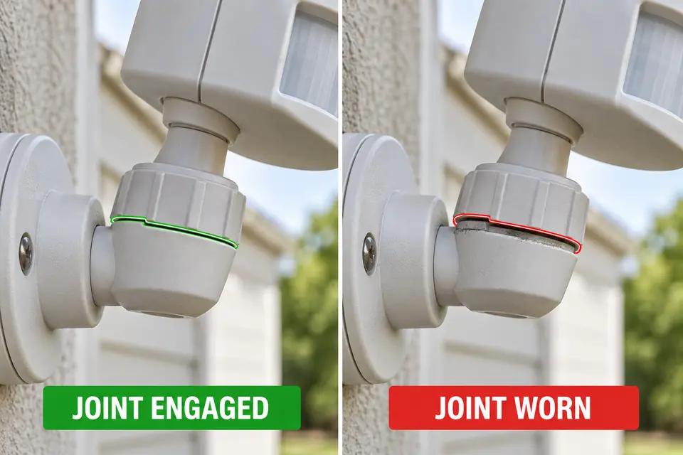
A joint that is merely loose should become progressively more secure as its locking part seats. A joint that turns without gaining holding force—or feels tight before it seats—needs closer inspection rather than more pressure.
The movable connection may be a ball-style knuckle, threaded stem, compression collar, serrated interface, or another manufacturer-specific design. In each case, the mechanism must create enough friction or clamping force to resist the weight of the sensor and ordinary outdoor movement.
A locknut or collar normally compresses or seats the movable parts after the angle is chosen. If that part backs off, sits crooked, or cannot reach its seating surface, the head may feel adjustable without ever becoming secure.
Read what the joint is doing
A serviceable joint normally develops clear resistance as the collar or locknut is tightened. The head moves while the joint is loose, then holds after the locking surfaces seat squarely.
A worn joint behaves differently. The nut may keep turning without increasing resistance, or it may reach the end of its travel while the sensor still moves. Flattened threads, a crooked collar, missing material, a widening crack, or a gap that never closes all point beyond routine adjustment.
Weathering can create the opposite problem: the hardware may seize before the joint is clamped. Corrosion around exposed threads can make a nut feel tight even though it has stopped short of its seating surface. Paint, mineral deposits, dirt, and oxidation can also hide the boundary between the movable and fixed parts.
Do not force seized hardware against an aging plastic or cast-metal housing. If the locking part will not move with restrained pressure, follow the separate guidance for fixture hardware that has seized from corrosion instead of using the sensor body as a lever.
A crack around the sensor stem or fixture-side socket matters more than surface discoloration. Tightening against a cracked connection can spread the damage, distort a sealing surface, or allow the head to separate.
Why Tape Is Not a Durable Fix
Tape may stop visible movement briefly, but it does not return holding force to the joint. Outdoors, its adhesive softens in heat, hardens in cold, collects dirt, and loses grip through ultraviolet exposure and repeated wet-dry cycles.
An external wrap also hides the evidence needed to judge the failure. It can retain moisture around the joint or conceal a crack that continues to widen.
Common mistake — supporting the head instead of repairing the joint
- Tape and adhesive transfer the load without restoring the locking mechanism.
- Wire, zip ties, and wedges can concentrate force on the sensor housing or lens.
- Fabricated braces may interfere with drainage, aiming, servicing, or the fixture’s weather barrier.
If the joint cannot hold through its designed locking parts, that result defines the repair boundary. An improvised restraint only delays the replacement decision while placing stress somewhere else.
Holding the Detection Zone Without Overtightening
The useful adjustment is the lightest one that seats the joint and holds the chosen angle. Extra force does not compensate for stripped threads, worn mating surfaces, or a cracked collar.
Field Check: Isolate power before touching or loosening hardware on a hardwired outdoor fixture. If the correct circuit cannot be identified, the fixture is above safe working height, or the complete unit moves at the wall, stop the adjustment.
Use this controlled sequence:
- Record the starting position. Photograph the head against a fixed part of the fixture and note the direction in which it normally drops.
- Support the sensor head. Hold its weight without pulling, twisting, or using the lens and housing as a handle.
- Loosen only the intended locking part. Move the collar, locknut, or clamp only enough to reposition the head. Do not open the wiring enclosure.
- Seat the joint squarely. Remove loose exterior debris if accessible, aim the sensor, and confirm that threaded or mating parts are not entering at an angle.
- Tighten with restrained pressure. Stop when the joint holds. Follow manufacturer instructions when available; there is no universal torque for mixed plastic, aluminum, and cast-metal sensor joints.
- Restore power and retest. Walk across the intended detection area, allow the light to complete its normal cycle, and compare the sensor position with the original reference.
The detection result matters only if the head remains at the chosen angle. If it misses the route but the reference position has not changed, the next decision concerns sensor operation or aiming the outdoor security light at the intended coverage area.
A head that sags immediately never developed holding force. One that drops gradually may have enough initial friction to feel secure but not enough sustained clamping force to carry its own weight. Both results point toward joint wear, damaged threads, incorrect seating, or a failed locking component.
One correctly seated adjustment is a diagnostic test. If the same joint needs tightening again after a few operating cycles or ordinary weather exposure, stop treating it as routine adjustment. Further force can strip the remaining threads, split a collar, or deform the fixture-side socket.
Replacing the Sensor Head or Fixture
Choose the replacement boundary by inspecting the fixed side of the joint. A new sensor head makes sense only when the fixture was designed to accept one and its mounting interface remains structurally sound.
Confirm compatibility through the fixture manufacturer’s documentation. The replacement must match the specified mechanical interface, supply voltage, permitted lighting load, control arrangement, weather rating, and sealing method. A stem that fits the opening does not prove its threads, gasket, electrical rating, or drainage orientation are compatible.
Replace beyond the failed part
Replace the complete fixture when the sensor joint is molded into an integrated housing, the fixture-side threads are stripped, the body has cracked around the joint, or the sensor cannot be removed without opening a nonserviceable assembly. Whole-fixture replacement is also the cleaner boundary when water has entered the enclosure or no listed compatible sensor is available.
A replaceable sensor cannot rescue a damaged attachment point. Installing a new head into distorted threads or a cracked socket transfers the same holding problem to the new component.
If the fixture body and attachment remain intact and the sensor is a documented service part, replacing only that component may preserve the rest of the unit. Because this work can involve line-voltage connections and weather seals, use a qualified electrician when internal conductors must be disconnected or the enclosure opened.
The wider outdoor-light repair-or-replacement decision becomes relevant when joint failure appears alongside water entry, deteriorated mounting hardware, damaged seals, or other fixture-level decline.
After an approved repair or replacement, check the physical reference before judging coverage. If the head holds, walk across the intended detection zone and evaluate its response. If it moves again, the mechanical repair has failed regardless of how the light behaved during one short test.
For general shock-prevention guidance around residential fixtures, consult the U.S. Consumer Product Safety Commission’s electrical safety guidance.