
Your landscape transformer shows an apparently normal voltage with the lights disconnected, then the reading drops when they are connected. The useful question is whether the failure follows a particular run or the amount of connected load. Removing a run changes both, so recovery alone cannot tell you which component needs attention.
First establish what “output drops” means. If you have only seen the fixtures dim or a display change, the broader low-voltage lighting diagnosis may be the better starting point. A reading at a distant fixture does not establish what is happening at the transformer.
Once the measurement location is clear, compare the configurations already associated with normal and abnormal operation. That evidence determines whether the next step belongs with an individual run, combined demand, or professional source testing.
No-Load Voltage vs Loaded Performance
Judge the reading by where it was taken and what was connected. A voltage meter draws very little current; operating the lights demands more from the transformer and every connection carrying their current. An unloaded reading establishes voltage at that point, but does not demonstrate the ability to sustain the installed load.
Some voltage change under load is normal. Whether it represents failure depends on the transformer’s specifications, output type, and permitted operating conditions. Some electronic supplies also have minimum-load requirements or behavior that makes an unloaded measurement unsuitable as a baseline.
If the source reading remains appropriate but the fixtures stay dark, the problem belongs closer to output voltage but no working lights. An interrupted circuit or poor downstream connection requires a different investigation.
A reading taken beyond a resistive connector includes the loss through that connector. It cannot, by itself, establish that the transformer’s own output has collapsed. Record where any existing readings were taken; do not open energized equipment to obtain a comparison.
A Weak Transformer and a Faulted Run Look Similar
The last run connected is a suspect, not a verdict. It may contain a fault, demand more power than expected, or simply push the combined load beyond what the system can sustain. A deteriorated shared connection can also become troublesome only when current flows.
The transformer remains a possibility, but so does its upstream supply. Until those are separated, “it cannot power the lights” describes system behavior rather than proving internal failure.
Removing one run eliminates that circuit and reduces demand. The following patterns help interpret that change without claiming more than the evidence supports.
| Observed pattern | What it raises | What it does not prove |
|---|---|---|
| One permissible run operates; adding another causes collapse | Added-run trouble or combined-demand limitation | The added run is faulty |
| Runs operate individually but fail together | Aggregate demand or shared-source limitation | Internal transformer failure |
| One run fails alone while another operates | Run-specific trouble, excessive run demand, or incompatibility | The exact failed cable, fixture, or splice |
| A professionally verified suitable load also fails | Source or upstream supply concern | Failed transformer windings without further checks |
The loads must also be comparable enough to support the conclusion. A small path-light run operating successfully tells you little about the source’s ability to support a much larger run. Passing a small test load does not certify full rated capacity.
Adding One Run at a Time
Identify the physical runs before changing the connected load. Start with the installation record, equipment labels, fixture demand, and recent lamp or fixture changes. A control app’s “zones” may share wiring, so independently controlled groups are not necessarily independent electrical runs.
Compare documented demand with the transformer’s instructions, including total capacity and separate circuit or output limits. When reviewing the connected lighting load, use the manufacturer’s loading and derating requirements rather than assuming a universal percentage applies.
Fixture wattage totals provide a useful starting point. They do not fully describe every LED driver’s startup behavior or current demand, and watts and volt-amperes are not always interchangeable. Check compatibility and any minimum-load requirement before interpreting a small isolated load.
Keep the existing tap selection and control settings unchanged. Do not raise the tap to compensate for unexplained collapse. Comparisons also need similar starting conditions: a transformer that has just shut down hot cannot be meaningfully compared with an earlier cold start.
Fix Boundary: Only change connections where the manufacturer permits access to an isolated, user-serviceable low-voltage area. Disconnect supply power before every change; a timer’s off setting is insufficient. Secure unused connections and restore covers before energizing. Hardwired equipment, exposed mains parts, or uncertain isolation require a professional.
Where that boundary is satisfied and there are no damage signs or previous protective trips, the comparison follows this order:
- Record the existing arrangement. Identify each run, its documented load, original connections, and symptoms already observed.
- Check permissible configurations. Confirm that an individual run and any proposed combination meet the manufacturer’s operating requirements.
- Observe one eligible run. With supply power disconnected, configure that run according to the instructions. Restore the enclosure before operating it.
- Add only after normal operation. Disconnect power before adding the next eligible run. Record which configuration changes the behavior, and stop at abnormal operation.
- Interpret the change before continuing. Consider both the added run and the new total demand. Further isolation belongs to a professional after a fault, trip, or uncertain result.
A sequence that works with Run A and fails with A plus B leaves two questions open: whether B introduces an abnormal load, and whether the combined demand exposes a shared limitation. That sequence alone cannot answer both.
If existing observations—or a professional’s controlled assessment—show that both runs operate individually but fail together, combined demand and shared-source performance become the focus. If one permissible run fails alone while another operates, investigate that run while accounting for differences in their loads.
Do not repeatedly recreate collapse to make the pattern more convincing. Preserve the observations; the next useful evidence may require current measurement or a verified test load rather than another restart.

Heat and Reset Behavior Under Load
Keep immediate collapse separate from failure that develops after operation. The first pattern directs attention toward the connected configuration and its electrical demand. The second adds temperature and protection behavior to the assessment; mixing them can make the same run appear responsible for different reasons.
Warmth alone does not establish a fault. If the transformer heats up and repeatedly resets, cooling recovery may support a temperature-related explanation—but only if that model’s protection operates that way.
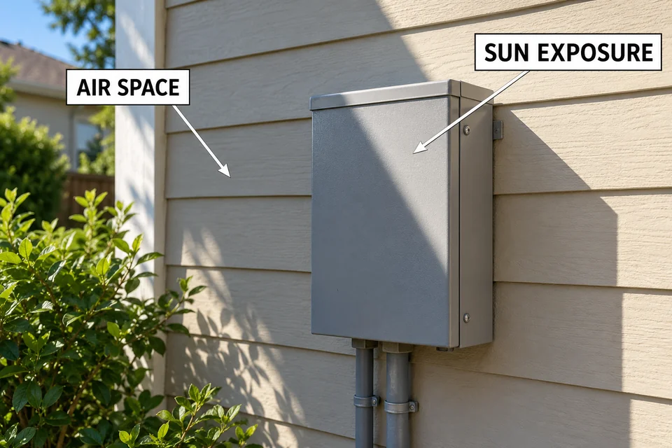
Record timing already observed, the connected runs, direct-sun exposure, and whether surrounding objects restrict air space. These details help explain why one observation differed from another. They do not establish that heat caused the output drop.
Burning odor, melted insulation, visible scorching, or repeated protective operation ends homeowner testing. Stop using the system and arrange assessment. Do not touch the enclosure to estimate temperature, wait for another shutdown, or treat recovery after cooling as permission to continue.
When Load Testing Requires Professional Equipment
Stop rearranging runs when the remaining question requires measuring demand rather than observing which lights operate. Professional testing is also the next step when connections are inaccessible, protection has operated, or output appears to fail with a load that should be suitable.
The technician needs instruments appropriate to the supply’s AC or DC output and waveform, along with the model’s operating specifications. Loaded voltage and current measurements can reveal information that an unloaded reading or fixture wattage total cannot.
A verified compatible test load helps separate the installed landscape network from the source. That assessment must also account for connection losses and upstream supply stability. Even failure with a suitable load does not justify blaming transformer windings before those possibilities are excluded.
Provide the model number, run inventory, recent fixture changes, and configurations associated with normal and abnormal behavior. Existing readings are useful when their measurement locations and conditions are known. There is no need to gather additional live readings yourself.
The repair decision should follow the evidence: investigate a run when the problem follows that run; assess demand and the shared supply when permissible runs fail together. Replace the transformer when testing identifies a source failure. Voltage returning after disconnection is a useful clue, but it is not enough to authorize that replacement.
For the mains-side boundary, FX Luminaire’s voltage-checking guidance assigns outlet-voltage testing to a licensed electrician.